
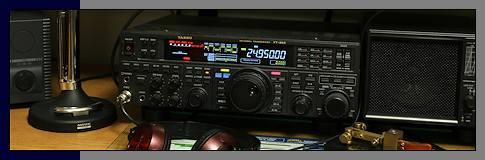

 Station AJ8MH - Marquette, Michigan")
Notebook Series - Linear-Loaded Vertical Doublet (Dipole)
[ Marquette, MI ] This is an update of my original vertical doublet design.
In Texas, I used a 32 ft vertical doublet and fed it with 300 ohm ladder-line. I always wanted to try
linear-loading this vertical doublet to make it more useful as a DX antenna on 30, 40 and possibly 80 meters,
but never got to it until now.
Here are a few things to remember while reading my notes.
1) The reason for this experiment was to find a small footprint, good DX antenna for 30, 40 and 80.
2) There isn't an antenna test range in my backyard.
3) All comparisons were against my 44' horizontal doublet when it was in use.
4) The basic antenna started in life as a 32.5', 20 meter homebrew vertical doublet.
5) Radials? Don't have room for them and never used them on a vertical doublet.
6) No attempt was made to resonate the antenna on a specific frequency, but I wanted to get it close to
40.
7) Vertical doublet balance is difficult to maintain for many reasons.
8) Any antenna that isn't full size is a compromise. How much of a compromise can be debated by
the engineers.
9) Antenna modeling wasn't used, but would have been nice. Antenna theory was thought about for a
very brief moment. Remember, contacts can be made using a wet string in a stiff breeze on a good
day.
Number six may sound strange, but I didn't want to pull the vertical down to do any trimming of the
linear-loading wires once in place. I just wanted to effectively lengthen the antenna and move the
resonant frequency toward the 40 meter band. I had a good idea of what resonant frequency to expect
based on prior results of others. Since I am feeding this antenna with ladder-line, the exact
final resonant frequency was not important to me.
 According the the ARRL
Antenna Handbook, linear-loading introduces little loss and has a low Q, which allows good bandwidth (up
for debate by a few). There are a couple ways to linear-load an antenna. I selected the one shown
below, which would shorten the overall length of the antenna the most. I elected not to run the
linear-loading wires all the way to the doublet extremes.
According the the ARRL
Antenna Handbook, linear-loading introduces little loss and has a low Q, which allows good bandwidth (up
for debate by a few). There are a couple ways to linear-load an antenna. I selected the one shown
below, which would shorten the overall length of the antenna the most. I elected not to run the
linear-loading wires all the way to the doublet extremes.
So, how long should the linear-loading element be? I picked 12.5 feet', simply because I wanted to run
the wire 3/4 of the way up and down each element. (Each loop used 25' of wire.) I figured this
would resonate somewhere between 7 and 10 MHz, and that was good enough for me. (Final "system"
resonance turned out to be 7.5 MHz. To bring this antenna into resonance at 7 MHz, the main element
would have to be lengthened a couple feet. It may be beneficial to add a top radial hat and bottom
radial shoes.)
So, what should the distance be between the linear-loading wire elements and the wire/aluminum
elements? 3" between the wire elements looked good to me, and I'd live with the distance created
between the wire and aluminum elements. How's that for solid engineering?
Some have used 450 ohm ladder-line for linear-loading elements with good results. I haven't heard of
anyone using 300 ohm line. I'm going to assume that the open-wire design I'm using isn't as sensitive
to rain and snow, thereby maintaining resonant stability.

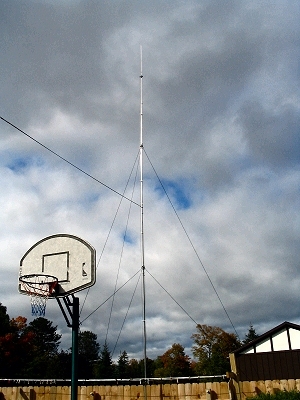
Overall length: 32' 6"
Each element length: 16' 3"
Each linear-loading element length: 12' 6" (25' in each wire loop)
Feedline: 100 Ft of 300 ohm ladder-line
Radial System: None
Matching: Homebrew balanced tuner
See the original vertical doublet design
for tube size and lengths.
 Construction details and photographs.
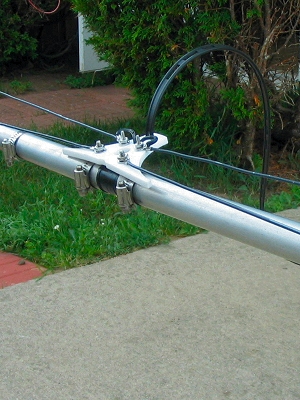
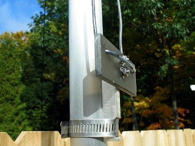
This is the center feed point showing how the linear-loading wires are connected. The two closest
screws in the center of the picture connect the wire to the aluminum element. The two other screws
connect the 300 ohm ladder-line to the wire.
The aluminum sections and the center Acetron insulator are hose-clamped. Each aluminum section is
slit, so they can be compression clamped.
All hardware is Stainless Steel.
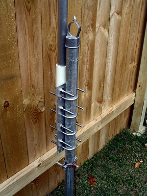
 This shows the linear-loading wires running
through one of several fiberglass spreaders.
This shows the linear-loading wires running
through one of several fiberglass spreaders.
The spreaders are 4 inches long with the holes drilled 3 inches apart. Each spreader is run through
aluminum supports that are hose-clamped to the vertical element.
The fiberglass rod is cut from the larger size driveway reflector supports.
One of the guy-ropes is also seen in this picture.
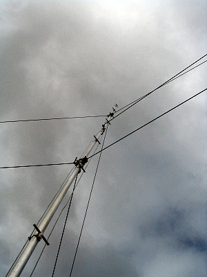
 The linear-loading end insulators are made
from aluminum and Plexiglas. Note the hose clamp guide cut in the aluminum.
The linear-loading end insulators are made
from aluminum and Plexiglas. Note the hose clamp guide cut in the aluminum.
The wire is simply looped through the Plexiglas and run back toward the center feed point through the
fiberglass spreaders.
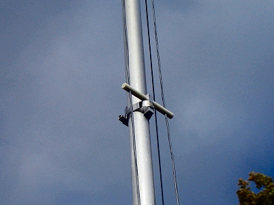
Below is a picture showing the linear-loading wires running through the spreaders. Shown below and to
the right is the base mount.
73,
Joe (AJ8MH)
ex: WPE8EUM, WN8AQL, WB5FCO and WJ5MH
*L. B. Cebik, W4RNL ~ 1939 - 2008 ~ SK as of April 2008
")

