
 Station AJ8MH - Marquette, Michigan")
Notebook Series - Horizontal and Vertical Doublets (Dipoles)
 [ Austin,
TX ] Here are two antenna projects that show the simplicity of home-brew antennas that perform
remarkably well. So, before you spend big $$ on commercial antennas, take a look at these.
[ Austin,
TX ] Here are two antenna projects that show the simplicity of home-brew antennas that perform
remarkably well. So, before you spend big $$ on commercial antennas, take a look at these.
While living in Texas and surfing the WEB, I ran across a site hosted by W4RNL.* One of his many pages
described a doublet that would fit in a limited city lot. I've played with a couple variations of his
44 ft and 88 ft designs, and they all worked great.
I've used open-wire feed, 300 ohm TV ribbon cable, 300 ohm ladder-line, and 450 ohm ladder-line with good
results. Of course, a balanced antenna tuner should be used with this type of antenna, and they can be
easily built, too. All my tuners use choke baluns. (Note: I haven't had any tuner heating
issues tuning these antennas. Also, auto-tuners may have issues, because of the impedance of the
antenna on some bands.)
Another interesting and surprising antenna is the vertical doublet. I used one for many years in Texas
(without radials) mounted just a couple feet off the ground.
 When compared to a horizontal doublet
at 19 feet above ground (neighborhood constraints), the vertical was superior for DX on 20 meters. This
antenna was a surprising performer. It even loaded well on 40 meters with a balanced tuner, and did a
respectable job. I've been thinking about linear-loading this type antenna, but haven't
followed-through.
When compared to a horizontal doublet
at 19 feet above ground (neighborhood constraints), the vertical was superior for DX on 20 meters. This
antenna was a surprising performer. It even loaded well on 40 meters with a balanced tuner, and did a
respectable job. I've been thinking about linear-loading this type antenna, but haven't
followed-through.
Note: I finally got around to linear-loading this vertical doublet after moving to Michigan, and
details are included in my Notebook Series - Linear-Loaded Vertical Doublet (Dipole)
Construction details can been seen to the left and below.
Notebook Series - The Inverted-L
 [ Marquette,
MI ] Don't have room for a full size 160 or 80 meter antenna? Want to capture a little DX
on these bands? How about an inverted-L? It's another simple antenna that does a good job.
[ Marquette,
MI ] Don't have room for a full size 160 or 80 meter antenna? Want to capture a little DX
on these bands? How about an inverted-L? It's another simple antenna that does a good job.
Here are some notes on my previous installation...
The basics: Each "L" and each elevated radial are a quarter-wave. That's 130 feet for 160 meters
and 67 feet for 80 meters. Cut the wire long and trim as necessary or use a tuner. The vertical
portion of the "L" should be as high as possible. Use the remaining length for the horizontal
portion.
For an efficient antenna, 3 or 4 elevated radials are required for each band. Because of yard
constraints, you may only use 1 radial for each band.
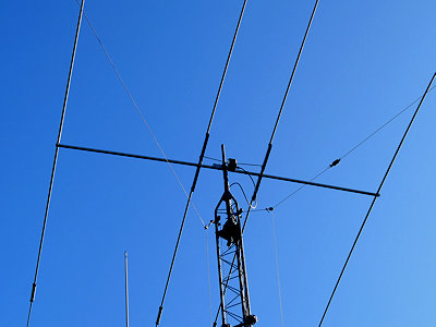
At one time, I used one feed-line for both inverted-L's, but decided on separate lines just to minimize
interaction between antennas. 50 ohm, 8 foot feed-lines ran from an auto-tuner in the shack to 1:1
chokes mounted on the 36 foot tower.
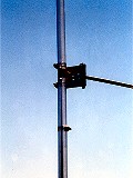
Each vertical leg ran up the side of the tower to the 32 foot level and separated from each other as much as
possible. Each wire passed through an insulator that was tied off to the tower top. This kept
each line a little over 2 feet away from the tower. The 80 meter wire continued horizontally to a
tree. The 160 meter wire continued to another tree. Each end was about 30 feet off the
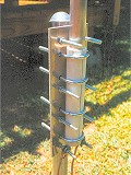
ground. A spring tension system inside PVC tubes was used at both feed-points.
Note the attachment points for the ends of each inverted-L and the above-ground radials in the pictures
below. I used a "T" pipe mounting off the side of the tower about 7 feet off the ground. All
wires were insulated from the pipe mounting. Look at the pictures to see how the radials ran along the
property fence line. Radials also ran out the side yard to a couple trees. One 80 meter radial
was bent 90 degrees. Radials were 7 to 10 feet off the ground. This is certainly not optimum, but
worked OK. Keep the elevated radials high so foot traffic can cross under the lines.
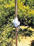
(September 13, 2017) I added static discharge components to both inverted-L antennas. I placed
them across the coax on the radio side of the choke in the junction box. One 2W, 1M ceramic composition
resistor and one 2700V gas discharge tube were placed in parallel and connected between the center conductor
and ground. You can see the components in the picture of the inverted-L junction box. The
components were tested at 500 watts, but watch for any strange behaviors. (Mouser Electronics: Ohmite
Resistor OY105KE - Bourns GDT 2095-270-BLF
(January 24, 2021) The above ground radials for the two inverted-L antennas were reduced to one radial
per band. The trees that supported the 2 radials for 40 and 80 meters had to be removed. Both Ash
trees were attacked by the Emerald Ash Borer (EAB), an invasive beetle in North America imported from
north-eastern Asia. Both trees died within a year of being attacked.


73,
Joe (AJ8MH)
ex: WPE8EUM, WN8AQL, WB5FCO and WJ5MH
*L. B. Cebik, W4RNL ~ 1939 - 2008 ~ SK as of April 2008


")


