
 Station AJ8MH - Marquette, Michigan")
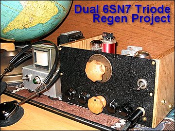
The Dual 6SN7 Dual Triode Regen Project From Start to...Finish
11/17/2006
 This project is just getting off the
ground, and the plan is to update this sheet during the next several weeks.
This project is just getting off the
ground, and the plan is to update this sheet during the next several weeks.
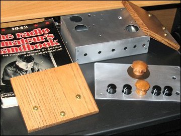
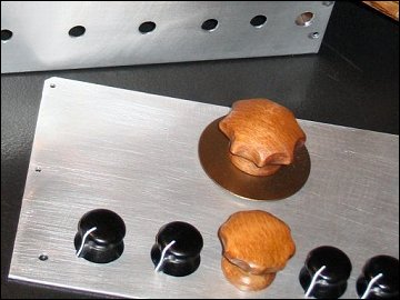
Wood side panels, and wood knobs for the main and bandspread controls have been finished. (The wood
knobs were made from cabinet knobs found at the hardware store. Edges were cut out and sanded.)
The other knobs have been cleaned and polished.
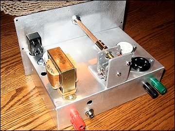
The initial layout has been put on paper and most of the holes have been punched or drilled. The main
tuning cap will be mounted under the chassis on the back wall, and the bandspread cap will be mounted on
top of the chassis toward the back on a bracket made from aluminum. The shafts running to the knobs
will be made from wood.
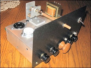 Space is a little cramped on the panel
around the volume and tone controls to facilitate room for the headphone jack. The switch for muting
the audio and T/R switching is on the panel above the chassis. This radio is small by my
standards.
Space is a little cramped on the panel
around the volume and tone controls to facilitate room for the headphone jack. The switch for muting
the audio and T/R switching is on the panel above the chassis. This radio is small by my
standards.
The front panel will be painted a black wrinkle finish. Of course, this must be done before the panel
and chassis are mated. Hardware will be added next.
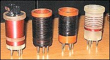
Parts have been dug out of boxes, but I'm waiting for some coil forms to be sent, and then I'll be ready to
experiment with the design.
Initially, I'll be using my bench supply for the radio, and I've included the schematic below.
11/26/2006
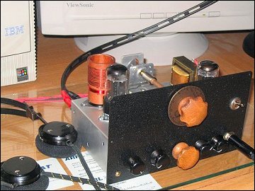
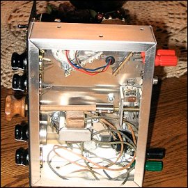 The front panel has been painted and all
the hardware has been added to the chassis. I've made the decal for the bandspread dial, but have yet
to install it on the aluminum plate. I'll complete the dial and install it this week.
The front panel has been painted and all
the hardware has been added to the chassis. I've made the decal for the bandspread dial, but have yet
to install it on the aluminum plate. I'll complete the dial and install it this week.
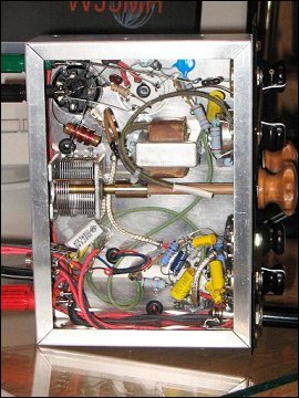
The next step will be wiring the radio, and this should be straightforward, because I've already made a
chassis layout. Wires and components were penciled in.
During the process of reviewing the schematic, I found B+ connected to ground. Not a good thing!
Several changes have been made to the schematic including clearing the short. Remember, this is not a
working radio. Design changes will be done after the smoke test.
The wires in the picture are from the two transformers, and they haven't been cut. The wood side
panels will be installed later.
11/27/2006
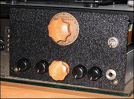 The dial has been installed.
Certainly not a National, but it serves its purpose nicely. I also removed the bandspread cap,
enlarged one of the holes for securing it to the support, and remounted it to straighten it out. I
added lock washers at the same time.
The dial has been installed.
Certainly not a National, but it serves its purpose nicely. I also removed the bandspread cap,
enlarged one of the holes for securing it to the support, and remounted it to straighten it out. I
added lock washers at the same time.
I also noticed that my DPDT switch for muting and controlling an antenna relay (if used) was inhibiting
installation of one of the 6SN7's. I had moved the switch back to make it flush with the mounting nut
on the front panel. I remedied the problem by bending the solder lugs to one side. Yes, layout
is important.
Looks like I'll be wiring soon, but my wife has me building bird-feeders out of plates and cups, so this
project is in a holding pattern, but hopefully only for a few days.
11/30/2006
It's working! More to follow. Schematic sheet has been been updated.
12/01/2006
 It's working, but I had a major issue
with the main tuning cap. I spent hours trying to stop the plates from shorting at different places
in the rotation. Talk about frustrating. I ended using a different cap, but it's slightly off
center to the front shaft, so more work needs to be done. (May I suggest that you use caps with wider
plate spacing's.) I've got room to change both the main and bandspread caps and may do that
later.
It's working, but I had a major issue
with the main tuning cap. I spent hours trying to stop the plates from shorting at different places
in the rotation. Talk about frustrating. I ended using a different cap, but it's slightly off
center to the front shaft, so more work needs to be done. (May I suggest that you use caps with wider
plate spacing's.) I've got room to change both the main and bandspread caps and may do that
later.
The radio is playing nicely, and I listened to 40 for about an hour. The RF amp isn't causing any
issues that I can tell. I had plenty of signals on the bench with a 10' wire, and when I connected it
to an 88' Zepp, I had to turn down the gain, but I didn't notice any pulling on 40 even with the high power
broadcasters. I will be looking at the amp to see just how much amplification is actually
happening. Also, using the gain control isn't shunting the RF to ground through the pot's
shell. I quickly parallelled 5K across the pot and the gain did not increase.
My power supply DC is a bit higher than expected using the isolation transformer. I figured I'd pull
more current, thus reducing the voltage. I wanted to see if using one of these transformers would
work.
The higher voltage (and probably more turns on the tickler) caused the regen pot to be ineffective. I
had to drop the value on the low side of the control to 5.6k from 10k to get enough headroom so the regen
could be adjusted.
The radio is far from done. I do need to look at the signal path, and check voltages at various
points, too. The audio doesn't sound distorted, but I'll check with a scope. It will drive a
speaker, but not a well as I would like. Yup, I'll stick with the headphones with 6SN7's. Both
the high and low Z phones work great.
12/02/2006
 The radio is done...for now. I
went completely through it and made some minor changes. They have been noted on the latest schematic
along with voltage measurements taken.
The radio is done...for now. I
went completely through it and made some minor changes. They have been noted on the latest schematic
along with voltage measurements taken.
I verified operation of the grounded-grid amp and made some changes to smooth the gain adjustment.
I did notice some distortion on CW when the signal is tuned for a low frequency note. This is not
being caused by the audio amp, but may be a result of the detector. I can see the distortion at the
RFC. Lowering the RF gain does help. Could it be front-end overload?
When I look at the resistance values used in the audio section, they don't look right to me.
Especially, the cathode resistors. The tube manual shows higher values, but I don't have a lot of
resistors to substitute with. What I did learn from playing with the RF amp is that the cathode
resistance really affects the plate voltage. It must be a juggling act to get it right.
Since I am not using the best power supply, there is some hum. I can eliminate it by shunting the
audio to ground at the first grid of the second 6SN7. The audio chain is running wide-open all the
time, so the hum is noticeable at low volume levels. I could probably wire the pot to pull audio for
the grid from the wiper through an additional cap. Many designs show the grid connected to the wiper
even without a cap, but I am unsure of the design.
I noticed that the regen control still didn't have enough headroom across the complete tuning range of the
radio. To fix for good, I removed tickler turns. I ended with a 4 turn coil.
I know you old regen folks have been through this before, but maybe new builders can gain some insight from
reading about this project.
Ya know, I may be able to make some contacts using this radio as the main receiver! A coil for 80 may
be next.
12/03/2006
I couldn't resist making just a couple more changes. I changed the cathode resistor on the first
triode of the second tube to 2k. I really wasn't happy with the plate voltage, but now it looks good
enough.
I also tried a 5 watt, 36 volt zener diode between the regen adjustment pot and the 47k resistor off
B+. It regulated the voltage fine, but really didn't make any difference in how the radio performed,
so I remove it. It would make more sense to regulate the entire supply voltage. I also added an
additional filter cap.
02/17/2007
I put zener back in and removed filter cap.) The schematic has been updated. Change is good.
01/14/2007
A coil to cover approximately 3 to 7 MHz has been completed and its measurements have been added to the
schematic. I also took some time to play with various resistor and capacitor values, but I didn't
find any substantial differences in operating characteristics, so I didn't permanently change any.
01/20/2007
I made reference in one entry note above about the way the volume control was wired. I changed it
tonight, and now the center wiper is connected directly to the grid, pin 1 of the second 6SN7. This
change eliminates hum at low volume levels. The schematic has been updated. Additional notes
have also been added.
02/17/2007
The bench power supply has been modified and the schematic updated. In the receiver, the coupling cap
to the high-Z output was changed to .22 uf. Look below for links to the schematics of the power
supply and receiver.
04/01/2007
A smaller power supply was built today to replace the large bench supply. The schematic has been
added to the downloads below.
04/15/2007
 I picked up two 5 pin forms at a local
hamfest yesterday, and quickly made a coil to cover 20 meters. The coil is 5 turns, wide-spaced to
cover about 3/4 inch on the form. The tickler is 3 turns close-spaced.
I picked up two 5 pin forms at a local
hamfest yesterday, and quickly made a coil to cover 20 meters. The coil is 5 turns, wide-spaced to
cover about 3/4 inch on the form. The tickler is 3 turns close-spaced.
I can tune from 11 to 22 MHz, which is much too broad, but I have some nice overlap with the other coils,
and I can also cover 17 and 15 meters. The main tuning capacitor I am using should be a smaller
value.
I noticed a couple issues. First, the bandspread needs to be expanded. In other words, the cap
value needs to be about half of what it is. Changing the design to allow for a cap to be added in
series with the variable bandspread when plugging in a coil would be ideal. This would allow
fine-tuning for each band of interest. Since I have one empty pin on each coil, I probably could make
that change without too much trouble. Notes have been made on schematic.
Also, the headphone cable seems to affect frequency stability on 20 meters. Simply turning my head
varies the frequency slightly. I have seen RF filters to isolate the audio output lines in some regen
designs, and now I know why.
04/26/2007
 What about the broadcast band?
When I was in my teens, I spent many hours tuning the BCB, so I felt an urge to use my last coil form to
wind an inductor to cover this part of the spectrum. My first attempt got me to 1650 kHz, so I
removed several turns to raise the frequency to about 1710 kHz.
What about the broadcast band?
When I was in my teens, I spent many hours tuning the BCB, so I felt an urge to use my last coil form to
wind an inductor to cover this part of the spectrum. My first attempt got me to 1650 kHz, so I
removed several turns to raise the frequency to about 1710 kHz.
I used number 30 wire and close-wound the coil to cover 1 3/8 inch of the form. I left 3/8 inch
spacing between it and the tickler. I wound a little more than 1/4 inch for it.
Finding that I couldn't tune all the way to 550 kHz, I had to come up with a method to add a capacitor
across the coil. If you look closely at the picture, you can see small banana jacks mounted on top of
the coil form. This allows me to try various values of capacitance to lower the frequency
range. The jacks are mounted on thick cardboard and held in place by wires running to the coil's
pins.
During a few short minutes, I logged California, Colorado, Ohio, Mexico and Cuba.
This is a fun radio!

")

