

 Station AJ8MH - Marquette, Michigan")
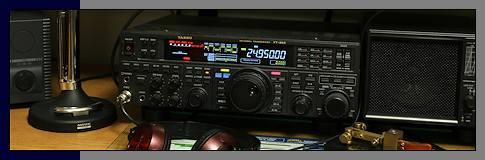
[ Yaesu FT-950/FTDX-3000 Notes and Other Tips ]
Notebook Series - Mating the Yaesu FT-950, Elecraft KPA-500 Amplifier and the MFJ-998 Auto-Tuner
 Mating the Yaesu FT-950, Elecraft KPA-500 and
MFJ-998 is relatively straightforward. Purchase the Yaesu 10 pin cable for the linear jack on the
FT-950, T9207451. Also, purchase a 15 pin female D-Sub connector with hood for the AUX port on the
KPA-500. If you plan on modifying the MFJ-988 for AMP inhibit, order 1N5711 Schottky diodes from
Mouser. (See AD5X MFJ-998 modification note below.) You will also need a two conductor cable
and phono plug for this connection. (This connection isn't necessary, but I like the idea of shutting
down the amplifier if the tuner decides to automatically start tuning.) Wire the cables as the
diagram indicates.
Mating the Yaesu FT-950, Elecraft KPA-500 and
MFJ-998 is relatively straightforward. Purchase the Yaesu 10 pin cable for the linear jack on the
FT-950, T9207451. Also, purchase a 15 pin female D-Sub connector with hood for the AUX port on the
KPA-500. If you plan on modifying the MFJ-988 for AMP inhibit, order 1N5711 Schottky diodes from
Mouser. (See AD5X MFJ-998 modification note below.) You will also need a two conductor cable
and phono plug for this connection. (This connection isn't necessary, but I like the idea of shutting
down the amplifier if the tuner decides to automatically start tuning.) Wire the cables as the
diagram indicates.
Please note that pins 3 and 8 of the FT-950 are paralleled and tied to ground, pin 5, on the KPA-500.
I looked at the FT-950 schematic and it appears pin 8 (FT-950 - TX Inhibit) can be left floating, but I
went ahead and grounded it anyway as recommended.
Change the following parameter settings in the KPA-500 menu.
RADIO=BCD (This allow the AMP to only receive data from the FT-950.)
BAND CHG = STBY (This will force the AMP to standby on every band change. Another safety
feature I like. There was a problem with firmware release 1.11 that wouldn't allow this, but it was fixed
in test release 1.16.)
INHIB IN=ENABLE (This will disable the AMP when a logic low is received from the auto-tuner.)

The AD5X modification to inhibit the KPA-500 amplifier during high SWR and tuning involves the addition of a diode to the amplifier-disable relay driver circuit at Q31. Tack solder the banded end of a 1N5711 Schottky diode to the ungrounded end of C164 located very near the front of K31. Solder a wire to the opposite end of the diode and run it to a phono jack on the back panel. You will need to add this phono jack. An ideal place for the phono jack is between and just above the two existing jacks. Plug a cable into this jack and run it to pin 11 on the AUX port of the KPA-500. Ground is pin 12. For a complete write-up, visit the AD5X web site.
Notebook Series - A Short Description and Fix for the Yaesu FT-950 Button Lockup Issue
My 950 front panel buttons started to lock up
more frequently over the past few weeks, and after yesterday they wouldn't unlock, so I decided to pay
closer attention to what was happening. Seems the same front panel buttons were locking up, so I
looked to see what was common to these. The buttons included NB, SPLIT, NAR, TXW, A-RX, A-TX and a
few others.
I backtracked the multiple logic paths from the front panel B unit through a short ribbon to the A unit and
over a long ribbon cable to the control unit. There, the signal went through a diode chip (three in
one), a logic chip called KEYDEC-1 then on to the u-processor. Since I don't have a scope or logic
probe, I was about ready to send it in, but...I decided to open the rig up.
I carefully removed the front panel enough to see the ribbon cable almost pulled from the connector.
I fixed that, but still had the problem. I reattached the panel. (Be careful with this
panel. The ribbon cable was pulled tight on mine and one of the small circuit boards made an
indentation in the cable. It would be better to remove this cable from the control board before
removing the front panel.)
I removed the bottom cover and followed the ribbon cable to the control board. The ribbon was pulled
tight and taped to the chassis. (I took the tape off to give the cable some breathing room.) I once
again applied power just to verify the problem was still there. It was.
I then took an insulated tool and poked around. Nothing happened until I hit the ribbon cable
connector on the control board. The buttons started to work. I powered down the radio and
looked over that area of the board with a magnifier, and didn't see a thing out of the ordinary.
Next, I removed the ribbon cable (pull up on the black bar) and cleaned the contacts with a small amount of
DeoxIT. I inserted the ribbon into the connector a few times then pushed the black bar back down to
lock it in place.
I reassembled the radio and (knock on wood) it's still working. Time will tell.
Front panel button lockup issue was first posted in November of 2010. I've seen many lockup issues reported
over the years.
Ribbon cable issues have been reported happening with many radios, not just Yaesu. Sometimes,
touching the cable with a diddle stick will pinpoint the exact ribbon cable that's giving you the
problem. (A diddle stick is actually just a small non-conductive screwdriver-like tool for making
fine adjustments to components inside the radio.) Use caution when removing the ribbon cable from the
connector. Some are locked in place and others are not.
Notebook Series - Build Your Own FH-2 Keypad
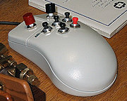 You can
build your own FH-2 keypad for the FT-950 and save a few dollars. The keypad is simply a bank of
precision resistors selected by pushing a momentary switch.
You can
build your own FH-2 keypad for the FT-950 and save a few dollars. The keypad is simply a bank of
precision resistors selected by pushing a momentary switch.
If you don't have a box of precision resistors, you can always place resistors in series or parallel to
come up with values that are close enough. The schematic shows all the values, but I only use #1
through #5-Store, #6-Memory and #12-Decrement.
You can build the keypad in almost anything, but I happened to have an old mouse that worked just fine as
you can see from the picture. A small circuit board will fit inside the mouse. The normal mouse
plastic push-buttons where glued before adding the new push-buttons. A mono plug was added to a new
cable and I was off and running.
Notebook Series - TX CW Carrier in all Modes (FTDX-3000 only)
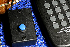 There are many times when you would want to transmit a CW carrier
while in any mode. The carrier could be used to initially tune an amplifier with low power or to
start a tuning sequence for a variety of external automatic antenna tuners. Adding a momentary switch
or pushbutton between pin 11 (TX REQ) and ground of the linear connector will transmit a carrier with
preset power from the radio. Go to menu #178 and select either 10, 20, 50 or 100 watts as your
default power. I selected 10 watts.
There are many times when you would want to transmit a CW carrier
while in any mode. The carrier could be used to initially tune an amplifier with low power or to
start a tuning sequence for a variety of external automatic antenna tuners. Adding a momentary switch
or pushbutton between pin 11 (TX REQ) and ground of the linear connector will transmit a carrier with
preset power from the radio. Go to menu #178 and select either 10, 20, 50 or 100 watts as your
default power. I selected 10 watts.
The FT-950 also has a TX REQ input, but on pin 10 of the linear connector. I haven't tried installing
a switch on the FT-950, and I don't have any idea of how to set low power automatically. This could
be a manual adjustment only.
Notebook Series - A Short Description of the Yaesu FTDX-3000 Transmit Final Amp Failure
I purchased an FTDX-3000 when Yaesu was giving a
$300 rebate back in 2016. After using the radio daily for a couple of months running 30 watts to
drive an Elecraft KPA-500, it developed an ALC/Power problem on 18, 21 and 24.5 mHz bands. From a
cold start at 100 watts CW keyed into a dummy-load, the ALC meter would show below the blue scale on these
3 bands. All other bands showed the ALC meter reading above the blue scale.
After several minutes, I'd key the radio and the ALC meter would show a decrease in ALC. In less than
an hour, the ALC meter would read nothing and the output power would be reduced to around 80 watts on the 3
bands in question. Other bands would remain at full power and normal ALC meter readings.
Setting the radio to 30 watts CW to drive the amplifier worked fine on all bands EXCEPT 18, 21 and 24.5 mHz
bands. Power would only be 10-15 watts output. RTTY and SSB power were also low on the bands in
question.
I sent the radio to Yaesu (close to $130 shipping) and the finals were replaced under warranty. I
never would have guessed bad finals with the indicated symptoms.
A couple other comments... I never use the analog meter display. I like to watch ALC and PO at
the same time, and these can only be seen together using the bar-display. I find the scope function
next to useless, and I've tried all the settings. Looks nice, but that's about it. I also don't
use the built-in CW, PSK and RTTY functions, since I use FLdigi with a home-brew interface. These
functions work great, I just don't use them. All other functions of the radio are great, especially
the receiver and its effective NB and DSP features.
Notebook Series - FTDX-3000 Flashing TFT Display
 My FTDX-3000 developed a "flashing screen" problem.
It was intermittent and happened after the radio was off for several weeks. (If I left the radio on
long enough, the screen would return to normal.)
My FTDX-3000 developed a "flashing screen" problem.
It was intermittent and happened after the radio was off for several weeks. (If I left the radio on
long enough, the screen would return to normal.)
I decided to replace the Display-1 "assembly" (see the service manual), and my TFT is now working
properly.
When you get the new display, remember to pull off the clear protective sheet. It's easy to
forget. When replacing the Display-1 assembly, it's best to remove the circuit board that holds the 4
pots located under the display, first. This board is only held in place by the nuts on the pot
shafts. I used a 10mm, "deep socket."
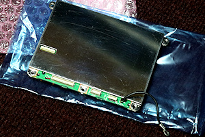
Remove all cables with caution. Remove 4 screws holding the small shield and set shield aside.
(Don't remove the large shield covering the Display-1 assembly.) Remove Display-1 assembly ground
wire from neighboring circuit board by removing screw. Remove 5 screws from Display-1 assembly.
Pull up on assembly near the pot circuit board. You have to pull up at a slight angle. The
Display-1 assembly may be stuck to the front window, because of foam. You'll see the foam I'm talking
about on replacement assembly.
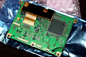
Once the new Display-1 assembly has been seated, use a very small amount of pressure to compress the foam
while tightening the 5 screws. Screw the ground wire to neighboring circuit board. Mount the
pot board. Again, use caution when plugging in the cables. (While the radio is open, clean the
ends of the ribbon cables with a very small amount of DeoxIT on a Q-tip.) Double check your work.
I did use a static wrist-strap when working on the radio... Try at your own risk. You're on
your own.
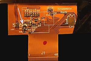 Update: I found a Russian
site that talked about TFT blinking. Don't know if it's the same as flashing, but he does have a
fix. It requires that the Display-1 board shield be removed to gain access to the Display-1
board. In my picture (bottom right) you can see the ribbon cable coming from the TFT in the upper
left of the screen. Under the black tape on the left side of ribbon cable there is a pot. (See
picture to the right.) That pot needs to be adjusted. Here is the Russian to English
translation:
Update: I found a Russian
site that talked about TFT blinking. Don't know if it's the same as flashing, but he does have a
fix. It requires that the Display-1 board shield be removed to gain access to the Display-1
board. In my picture (bottom right) you can see the ribbon cable coming from the TFT in the upper
left of the screen. Under the black tape on the left side of ribbon cable there is a pot. (See
picture to the right.) That pot needs to be adjusted. Here is the Russian to English
translation:
"yesterday this blinking won.. this is a problem with the display itself.. it is necessary to disassemble
the front.. get the display itself.. connect from the inner side.. remove the black sticker from the smd
potentika.. turn on.. in the menu, put item 9 (dimmer TFT) on 8.. twisting this potentik to make the
flicker disappear.."
Looks like a big job.
Notebook Series - Use of u-Tune Ports on Yaesu Transceivers
 The u-Tune Ports on the FT-950, FT-1200 and the FTDX-3000
can be used for something other than their intended purpose. I use mine to connect an MFJ-1026 Noise
and Interference Canceler, and a K9AY Loop Antenna control box.
The u-Tune Ports on the FT-950, FT-1200 and the FTDX-3000
can be used for something other than their intended purpose. I use mine to connect an MFJ-1026 Noise
and Interference Canceler, and a K9AY Loop Antenna control box.
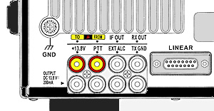
Looking at the back of the FTDX-3000, you will see two rows of RCA jacks on the left side. The u-Tune
output (to u-Tune hardware) and input (from u-Tune hardware) jacks are located ABOVE the 13.8 VDC and PTT
RCA jacks, so be careful when connecting to the u-Tune jacks. The u-Tune DIN jack is not used.
You can test the RCA u-Tune ports by turning on the ports. Press and hold the /uT button. It's
just to the left of the CLAR/VFO-B control. When this button is pressed and held, the receiver will
go dead. Now, loop the u-Tune input and output RCA jacks with a short length of coax, and the
receiver will come to life. You have just completed the RX RF path. Now, remove the loop and
connect your noise canceling unit. Be sure to get the "to" and "from" correct.
When these ports are used, you are only in the receive path. No transmit energy is present.
Download the diagram to see how it's done. ( Port Diagram )
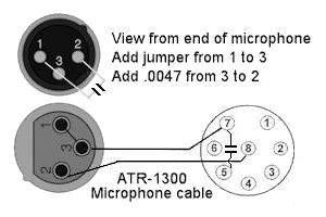
Notebook Series - Using the Audio-Technica ATR-1300 Microphone
 The Audio Technica ATR1300 is a dynamic unidirectional
quality low cost microphone (about $20.00) with a frequency response of 70 - 12,000 Hz and an impedance of
500 ohms. It's supplied with a 16 foot cable (XLR to 1/4 plug), and adjustable stand clamp.
The Audio Technica ATR1300 is a dynamic unidirectional
quality low cost microphone (about $20.00) with a frequency response of 70 - 12,000 Hz and an impedance of
500 ohms. It's supplied with a 16 foot cable (XLR to 1/4 plug), and adjustable stand clamp.
Interfacing this microphone to the FT-950 is easy. All you need is an 8 pin microphone connector and
a couple capacitors. First, determine how long you want your cable to be. Cut the cable the
required length keeping in mind that you'll want the XLR female connector on one end and the added 8 pin
microphone connector on the other. (Place the remaining cable and 1/4 inch plug in the spare-parts
bin.) Connect audio high to pin 8 and audio low to pin 7. The XLR female connector end of my
cable has pins 1 and 3 shorted together and connected to the shell. This is audio low/ground.
The FT-950 and some other Yaesu radios are very susceptible to RF affecting the transmit audio. I
noticed when I operated on 75 meters (I do maybe twice a year!), I heard RF when using the amplifier.
Placing a physically small .047 uf cap between mic low (pin 7) and chassis ground (pin 5) inside the 8 pin
connector fixed the problem. Any RF riding the shield of the mic cable is shunted to chassis
ground. Note, shorting mic low (pin 7) to chassis ground (pin 5) did not correct the problem.
Also, disconnecting mic low (pin 7) and running mic low directly to chassis ground (pin 5) did not correct
the problem.
Next, remove the screw on the microphone that holds the recessed XLR male plug. Gently remove the
connector from the microphone shell. Solder a .0047 capacitor across pins 2 and 3. This will
also help eliminate RF noise. You can also add a shorting wire from pin 1 to pin 3 of the male XLR
plug, but this is just insurance, since inside the XLR female receptacle on the cable, pins 1 and 3 are
already shorted together and connected to the shell.
If you're still experiencing RF feedback, you can add a couple Ferrite clamp-on-cores to the microphone
cable. I didn't need them, but added them anyway. I used low frequency type 75 material cores
(Fair-Rite number 475181651). Use different material if you're having problems on higher
frequencies.
If you're interested in limiting the low frequency response of the microphone, unsolder the red wire from
pin 2 of the recessed XLR male plug and add a .1 uf capacitor to this pin. Solder the red wire to the
other end of this capacitor, and insulate with shrink tubing.
I thought about using the microphone on/off switch to switch a capacitor in and out of the audio line, but
this switch doesn't open and close the audio path. It actually grounds the audio path. I found
it too difficult to access the switch to modify the connections.
That's it.
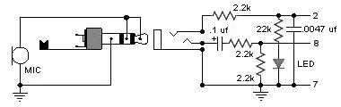
Notebook Series - Electret Headset Adapter
 Here is a simple adapter that will allow you to use cheap
Electret computer headsets with the Yaesu FT-950, FTDX-3000 and possibly other Yaesu rigs. Install
this circuit in a small plastic box and you're ready to go. Power for the headset comes from the
microphone plug. The .1 uf capacitor (watch polarity of cap) limits low frequency response and the
.0047 uf cap helps eliminate any RFI. RFI can be a problem with these Electret microphones, so you
may have to use small Ferrite snap-on cores on the leads. Watch your microphone gain, too. The
LED reminds you that the adapter is still plugged in. The LED should not be use on rigs that have
limited current handling capabilities on pin 2. For PTT, I use a foot switch connected to PTT on the
back of the rig.
Here is a simple adapter that will allow you to use cheap
Electret computer headsets with the Yaesu FT-950, FTDX-3000 and possibly other Yaesu rigs. Install
this circuit in a small plastic box and you're ready to go. Power for the headset comes from the
microphone plug. The .1 uf capacitor (watch polarity of cap) limits low frequency response and the
.0047 uf cap helps eliminate any RFI. RFI can be a problem with these Electret microphones, so you
may have to use small Ferrite snap-on cores on the leads. Watch your microphone gain, too. The
LED reminds you that the adapter is still plugged in. The LED should not be use on rigs that have
limited current handling capabilities on pin 2. For PTT, I use a foot switch connected to PTT on the
back of the rig.
Yaesu pin-out:
Pin 2 is +5V
Pin 8 is Mic Audio
Pin 7 is Mic Ground
Notebook Series - Audio to PTT Converter (FLdigi)
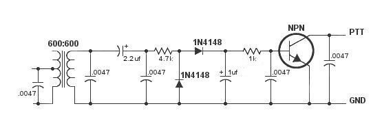 If you would like to use FLdigi for CW, you need a way to convert the CW tone
to key the transmitter, and this circuit is just what you need.
If you would like to use FLdigi for CW, you need a way to convert the CW tone
to key the transmitter, and this circuit is just what you need.
FLdigi can use 2 outputs from the sound card, and the manual can be a little confusing. You can use
the LEFT channel for both Digital (AFSK) and CW (CW Audio), but if you run CW audio tones directly into the
transmitter you run the risk of distortion from audio harmonic content. So, for my configuration, I
use the LEFT channel for the digital modes (RTTY, PSK, etc) and the RIGHT channel for CW and convert the CW
audio to a keying signal. If you look at Sound-card Settings (Audio Settings - Right Channel), you
must check "CW QSK signal on right channel."
Feed the audio from the PC sound card RIGHT channel to the center tap on the audio transformer. The
audio must be rather high so the sound can be rectified and converted into a DC level that will allow the
transistor to conduct.
Component were modified on Mar 24, 2017. The RF bypass capacitors (.0047uf) may be needed depending
on how much RF you have floating around in the shack. The 1uf filter capacitor seems to give me the
best timing.
FTldigi Modem - Timing and QSK Settings: 30% Weight, Blackman Edgeshape, 3.3 Dash/Dot, 8 Edge Timing,
100 BPF, Check BPF Transmit audio, Check Edge Decrease, and Check QSK on Right Channel.
Notebook Series - Computer/Radio Interface (FLdigi)
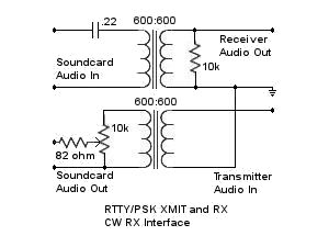 Here is a diagram of a simple RTTY/PSK audio interface. In fact, it can
be used for any of the digital modes including CW receive. The .22 uf capacitor is used to roll-off
low frequencies. It also gives some DC isolation if you're running audio into the mic input.
You may also need DC isolation connecting to some transmitter audio circuits.
Here is a diagram of a simple RTTY/PSK audio interface. In fact, it can
be used for any of the digital modes including CW receive. The .22 uf capacitor is used to roll-off
low frequencies. It also gives some DC isolation if you're running audio into the mic input.
You may also need DC isolation connecting to some transmitter audio circuits.
I happen to use the LEFT sound card channel for audio input and output with FLdigi. See "Audio to PTT
Converter" above for information on transmitting CW using FLdigi.
The receive audio level to the sound card can usually be adjusted from the radio's menu. Transmit
audio can be adjusted by the sound-card setting, the control in the interface and sometimes by the radio's
menu.
The radio's VOX mode can be used to key the transmitter when tones are sent.
To avoid splatter, always remember that correct transmitter level adjustment is critical. Usually,
you adjust the transmitter for rated power. Probably, 100 watts. Now, adjust the audio level
for 20 watts (or lower) output. Do not allow the level to cause any ALC reading. Reduced
transmitter power is always required, and it can be controlled by the audio input level to the transmitter.
Notebook Series - Modification to the MFJ-993B Auto-Tuner
My MFJ-933B was having a problem with erratic
tuning on two different doublets fed with 5 foot runs of RG-400 to remote toroid chokes. After doing
a web search, I found a site that suggested using shielded cable as a means to eliminate random switching
of the internal relays. I didn't have that problem, but I suspect I did have some RF getting into the
board after the forward and reverse sensing circuit.
First, I tried tightening the screws that hold the board to the chassis. Next, I tried re-positioning
wires, including the wires from the toroid used in the forward/reverse circuit. I also did a complete
alignment.
The MFJ-993B auto-tuner has two unshielded wires that connect the tuning capacitors to either the input
(low-Z) or output (high-Z) of the inductor string. These wires were blue in my tuner and switched by
K19. You can replace these wires with double-shielded RG-400 or similar cable. Each cable
should be grounded to the chassis at one location. Look closely at the picture and you can see the
coax outer cover has been removed to get access to the shield for grounding.
Tom, W8JI (who wrote the matching logic algorithms for this tuner) commented, "Adding coax at that point
will significantly reduce the capacitance range when you get to the low pF tuning steps. One logic
position is simply the stray capacitance of the relays and the wire to the relay. By adding coax you
decrease the minimum C." So far, I haven't seen any problem with matching, and the auto-tuner is now
stable.
The red, black and white wires are switching control wires.
A short note about the SWR bridge alignment. I did notice that when doing the "CAL CAP AND FWD"
adjustment, the "reflected meter movement" was NOT "exaggerated" as stated in the manual. The
reflected power NULL seemed rather broad, so I adjusted C91 NULL to coincide with a transmitted peak power
reading. (The peak change was only a couple watts in forward power with a very minor adjustment of C91. The
NULL in reflected power never changed.) The only time I saw any reflected power during the alignment was at
the extreme settings of C91.
I've noticed that the forward power reading is highly dependent on the reflected power reading, but not
nearly as much as when I first used the 993B. The forward power will read low depending on match, but
within 15 watts of of my transmitter indication at 100 watts with a 1.3:1 match. With a 1:1 match,
the power is dead-on. The digital display and the watt-meter track, and the frequency readout is
accurate.
Tom, W8JI says, "The REAL forward power of a system is the forward power of the directional coupler MINUS
the reflected power." The firmware is supposed to do the math to read and display real forward
power. With 3 watts reflected I would expect to see 97 watts forward power, but that is not the
case. The current forward power reading is good enough as is.
Also, the MFJ-993B doesn't read peak power, so I added a PDC-1 board to the tuner and that information can
be found here.
Notebook Series - Monoprice 4-Channel Headphone Amplifier
This is a schematic diagram for the Monoprice
4-channel headphone amplifier. (Other name-brand units seem to be similar from looking at the back
panel.) This diagram is my attempt at tracing the circuit, so the diagram may have some errors, but
it's close. It only shows one of the 4 op-amps used, and it doesn't show all the inputs and outputs
or the stereo-mono switch.
The idea was to use this amplifier with my rig so audio could be shared between four operators. When
I initially plugged the unit in, I noticed RF was getting into the op-amps when I was running at transmit
power levels near 500 watts. I added by-pass capacitors to all the input lines, but still had a
problem. I found that changing position of the headphone leads would cause a change in the RF
interference level, so I decided to place .001 capacitors across the output.
I read a long time ago that doing this could cause oscillations, but so far I haven't heard any in my
headphones or while tuning across the VLF and broadcast band frequencies. The audio waveform looks
good using computer audio processing software.
Placing the capacitors across the output greatly reduced the RF interference level with just a very minor
amount still heard on 80 meters. To eliminate that, I added ferrite beads to the output.
(Fair-Rite p/n 2673021801.) I used two turns of enamel wire through the small type 73 bead. I
lifted the output side of the 10 ohm resistor and placed the FB between it and its old mounting
hole.
Note, that I use two inverted-L antennas for operating on 160 through 30 meters, and the base of these
antennas is right out my operating position window.
I also modified the amplifier audio input to limit the low frequency response. This amp has two
inputs. There are two RCA jacks, and a standard 1/4 inch stereo jack. They both fed the same 1
uf cap, so I opened the circuit board trace from the 1/4 inch stereo jack and installed a .1 uf across the
open. Now, I use the stereo jack to connect to my radio and if I ever want to connect it to a music
system, I can use the RCA jacks.
The amplifier does come with an 18 volt wall transformer, but I use my 13.8 volt distribution feed
instead. The amplifier does have a 12 volt regulator built-in, so regulation is marginal with an
input of 13.8 volts. .1 uf caps were install at both the input and output of the regulator.
This 4-channel headphone amplifier is built very well and sounds good, too. It's built in a metal
case, but of course, it's not designed to be used around an environment where RF levels are high.
CAUTION: Look at the diagram and you'll see that the jack output sleeve is NOT connected directly to
ground. All headphone jacks are connected through a 1000 uf capacitor. I replaced this cap with
a 100 uf to try and reduce thumping while CW keying. This value of this capacitor further reduced the
low frequency response. (Connecting a stereo cable from this point to a grounded audio device will
result in no audio...and maybe smoke.)
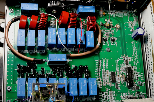
Notebook Series - Hy-Gain Ham IV Rotator Control Box RFI
 I use two inverted-L antennas with the vertical radiators
running up the side of the tower. The vertical elements are within two feet of the tower, the RF
feed-lines, and the rotator control cable. Unfortunately, the close proximity of the inverted-L
antennas to this control cable induces RF into the control box. This causes the meter to react to
transmitted RF even with the control box turned off.
I use two inverted-L antennas with the vertical radiators
running up the side of the tower. The vertical elements are within two feet of the tower, the RF
feed-lines, and the rotator control cable. Unfortunately, the close proximity of the inverted-L
antennas to this control cable induces RF into the control box. This causes the meter to react to
transmitted RF even with the control box turned off.
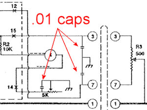
To fix the problem, I installed .01 capacitors from pin 3 and 7 of the control cable receptacle to ground
inside the control box. (I added a ground lug to the top female receptacle mounting screw.)
This bypasses the wires coming from the direction indicator control (R3 - 500 ohm) inside the actual
rotator. I also bypassed the 5K calibration pot using another .01 capacitor. As usual, keep the
capacitor leads short.

")

