

 Station AJ8MH - Marquette, Michigan")
Notebook Series - Mosley TA-33-M-WARC Installation
[ Marquette, MI] This is a pictorial of my Mosley TA-33-M-WARC
installation in 2011. The installation instructions that come with the antenna are
straightforward. Read them carefully.
First, a few general comments: The antenna boom to mast U-bolts and plastic clamping blocks only accept a 1
1/2 inch OD mast, which was not available locally, so I had to order a five foot section. The mast was
less than the cost of shipment. I suggested to Mosley that machining a boom to mast clamp for 2" OD
pipe would be more beneficial, because suitable pipe from local hardware stores could then be used for the
mast.
You first assemble the boom followed by the blue coded front radiator.
This is the driven element for 20, 15 and 10 meters, and is the first time you will decide on what
pre-drilled holes to use. Mosley suggests (it appears to be the only option) using the "phone" setting
for all around band use since the antenna is so broad. (In my installation the SWR was 2.0:1 at 14.0,
2.2:1 at 21.0 and 1.83:1 at 28.0.0 MHz. This isn't very good for a CW guy, but I'll live with it.
Your solid state transceiver or amp may not, and you'll need a tuner. Mine is an MFJ-998. SWR in
the phone segment of the band is fine. Mosley should clarify their suggestion, especially if an antenna
is mounted under forty-five feet.) The front radiator is then mounted to the boom.
The red coded back radiator is built next. This is the driven element
(dipole) for the WARC bands, and there is only one setting for this element. Follow the directions for
mounting it to the boom and connecting the phasing lines. Look at my pictures below to see how I
simulated a mast with PVC. I did this to insure the phasing line closest to the mast does clear the
mast. Note, this element is shorter than the front radiator, so it does look strange mounted between
the reflector and the front radiator.
Next, assemble the black coded director. Again, Mosley says to use the
"phone" setting. Next, assemble the brown coded reflector. This
will be your longest element and Mosley has you set this to the "CW" setting and NOT the "phone" setting used
previously on the front radiator and director.
Now, mount the director and reflector to the boom using the supplied U-bolts and the #40 ALUMINUM clamping
blocks. (Do not use the plastic clamping blocks here. They are for the boom to mast
mounting.) SWR was flat in the phone portion of 20, 15 and 10, and flat across 17 and 12 with the
antenna mounted at 36 feet.
( Update: June 20, 2017) The top boom-to-mast U-bolt broke this month
after a little over five years of service. This could have been a catastrophic failure, but the bottom
U-bolt held. Reason for the failure is unknown, but you should use caution to make sure you don't over
torque these when tightening. Stainless steel is not nearly as strong as carbon steel in sheer strength
and if it's over-torqued, it will yield, weaken and later break off. Some have suggested using Penetrox
on the threads, but I didn't. I checked to make sure the old nuts weren't seized up. They were
relatively easy to loosen, so I doubt I had them too tight. All the boom-to-mast hardware, and plastic
spacers have now been replaced with genuine Mosley parts. I did add some stainless steel lock nuts
(kind with the Nylon inserts) after each lock washer and nut. Maybe this was just a fluke. These
U-bolts are only 1/4-20 x 1 1/2".
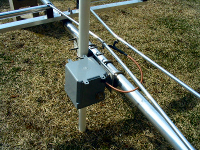
( Update: January 29, 2021) I've had a few questions about the choke I
used for the installation. Based on Jim Brown's (K9YC) tutorials, I used 4 turns of RG-400 (or its
equivalent) through 5 each #31 2.4" cores. I can't remember which cable I used since I had a couple
different versions available. The cable is continuous from the feed-point through a small hole in the
box, around the cores, then to the UHF Female Chassis Mount Connector (SO239-Teflon).
I have since gone to using a single big #31 clamp-on core for all my antennas with a different number of
turns for each antenna. I just haven't changed the choke on the beam since I put it up. If I
where to change the choke on the beam today, I would use one big core and 5 turns of RG-400.
Part Numbers:
1) #31 2.4" toroid (Fair-Rite #2631803802)
2) Buy one #31 "biggest clamp-on" for every three toroids (Fair-Rite #0431177081)
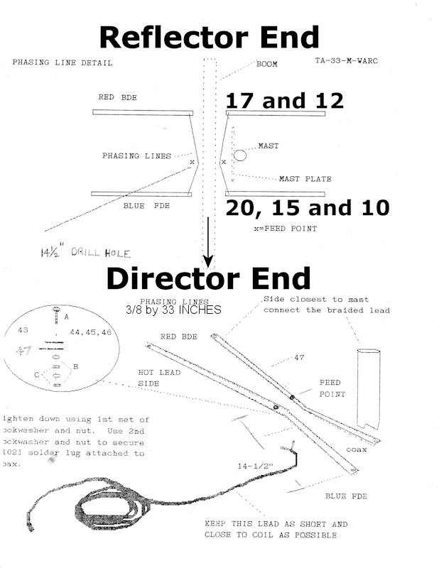
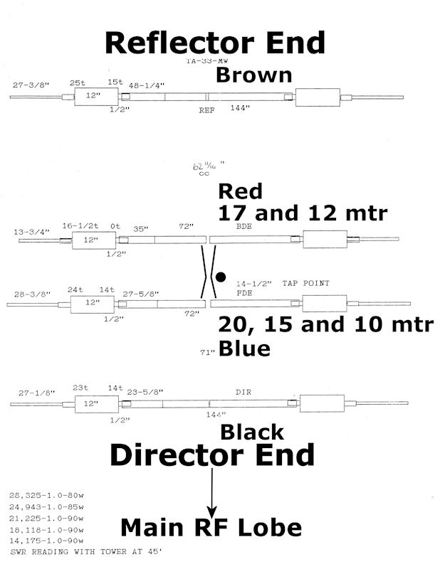
( Update: September 27, 2021) There have been a few questions about the
installation manual concerning the 17, 12 meter driven element, the 20, 15, 10 meter driven element, and the
phasing line between them. I've included pictures below that include notes from 2 pages of my
manual.
73,
Joe (AJ8MH)
ex: WPE8EUM, WN8AQL, WB5FCO and WJ5MH
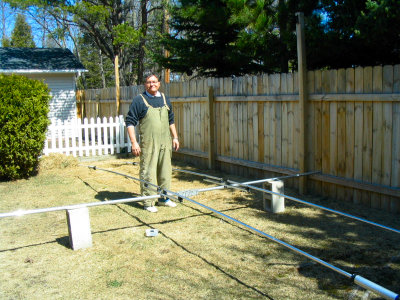
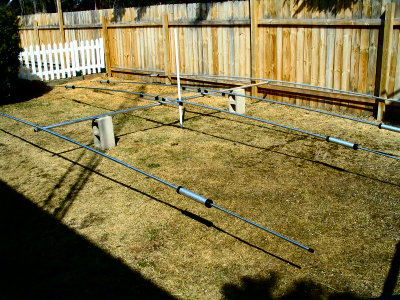
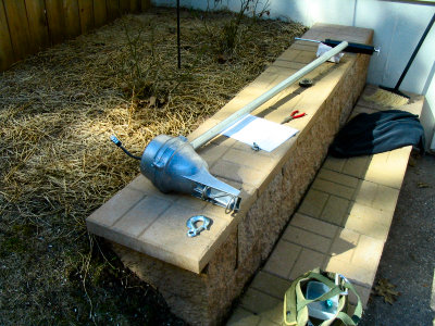
Staging area with a couple cement blocks. Works great. - Using PVC pipe to simulate mast. RF choke is in box.
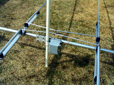

Close shot of choke and phasing lines. - Rotor and mast getting checked out.
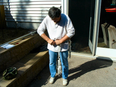
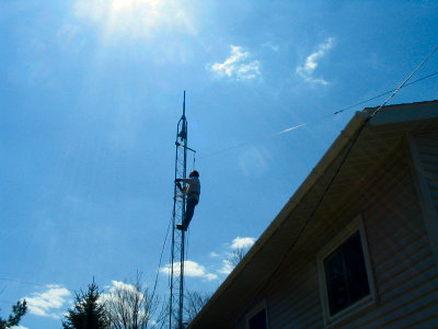
I can do this. Checking belt before climb. - Ready to install rotor.
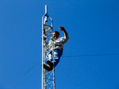
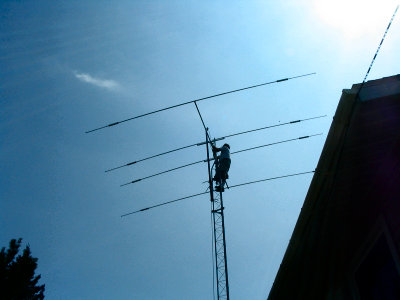
Rotor and mast installed. Pulling down inverted-V. - Lowering antenna over mast. Note gin-pole.
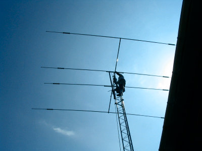
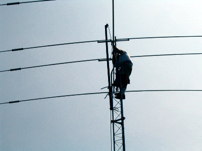
Adjusting height and U-bolts. - Trying to get mounting blocks between mast and boom. About done.
")

