

 Station AJ8MH - Marquette, Michigan")
Micro Satellites AO16 and LO19 (Non-Operational)
 PACSAT and LUSAT are two MicroSatellites that were launched along with other satellites from
Kourou, French Guiana, South America. An Ariane vehicle of the European Space Agency carried the
satellites aloft on February 22, 1990 to a low altitude, sun-synchronous, near polar orbit. Each
satellite takes a little more than an hour and a half to circle the earth at an altitude of nearly 500
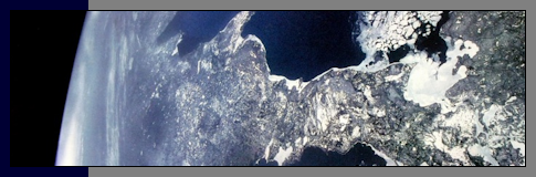
miles. Midday, you'll find the satellites passing north-to-south over the continental United States,
and in late evening, the satellites will pass overhead traveling in the opposite direction.
PACSAT and LUSAT are two MicroSatellites that were launched along with other satellites from
Kourou, French Guiana, South America. An Ariane vehicle of the European Space Agency carried the
satellites aloft on February 22, 1990 to a low altitude, sun-synchronous, near polar orbit. Each
satellite takes a little more than an hour and a half to circle the earth at an altitude of nearly 500
miles. Midday, you'll find the satellites passing north-to-south over the continental United States,
and in late evening, the satellites will pass overhead traveling in the opposite direction.
The satellites are amazingly small. They're cubed shaped, and approximately nine (9) inches on edge. In
fact, the 145 MHz. receive antenna is twice the length of the main body of the spacecraft. This single
element 1/4 wave antenna is located on the top (+Z surface) of the structure, and the four (4) shorter 437
MHz. transmit antennas are located on the bottom (-Z surface). All the antennas are made of flexible
metal much like the curved tape measures used by carpenters.
Attitude stabilization and control is maintained by four (4) small permanent magnets aligned
top-to-bottom. With this configuration, the satellite rotates end-over-end twice per orbit as it tries
to align with the earth's magnetic field. To reduce temperature variations on internal hardware, the
spacecraft slowly spins. This is accomplished by the 145 MHz. antenna acting as a radiometer. One side
of the antenna is painted white and the other black. Solar radiation pressure then causes the craft to
spin.
Each spacecraft is powered by eight (8) NiCd batteries. The batteries are charged by 440 small solar
cells mounted on all surfaces of the structure. The 22 volt battery bus is converted to 10, 8.5 and 5
volts DC. The CPU is an NEC V40. 2K of ROM is used for restart and approximately 10.5M of static RAM is
used for storage and the operating system.
PACSAT and LUSAT have been designed to provide AX.25 packet communications in the form of an orbiting mailbox
where messages are up-linked, stored and then forwarded to other Amateur Radio Operators anywhere on the
planet. Each satellite has the capability of receiving on four different frequencies simultaneously in
the 145 MHz. band. Ground stations transmit on one of these frequencies using Manchester encoded FM at
+/- 3 kHz. deviation. All ground stations listen to one down link frequency near 437 MHz. using a
single-sideband receiver and a special PSK modem. Communications is full duplex.
Special software is required to handle the protocols used with this form of satellite communications.
The software must be capable of using Broadcast and FTL0 protocols. PG, PB and Wisp are a few of the programs
available. This software can also be used to download telemetry files generated every minute or
so. These broadcasts give a snapshot of how the spacecraft is functioning. An example of a
typical telemetry download is shown below. Note references to battery voltages and array charge
currents. By looking at the charge current number, you can actually tell which side of the spacecraft
is facing the sun.
Telemetry - 57 Sample Peg Counts
| Data | Data |
|---|---|
|
|
 This has been a very brief description of two micro-satellites used by Amateur Radio Operators around
the world. For more information about the Amateur Satellite Service, visit AMSAT.
This has been a very brief description of two micro-satellites used by Amateur Radio Operators around
the world. For more information about the Amateur Satellite Service, visit AMSAT.

")

