

 Station AJ8MH - Marquette, Michigan")
AT-1 Transmitter by Heathkit
My Heathkit AT-1 project
The Heathkit AT-1 Transmitter Kit... The lowest possible dollar-per-watt price in the early
50's. "Panel mounted crystal socket, stand-by switch, key click filer, A.C. line filtering, good
shielding, etc. VFO or crystal excitation--up to 35 watts input. Built-in power supply
provides 425 volts at 100 MA. Amazingly low kit price includes all circuit components, tubes,
cabinet, punched chassis, and detailed construction manual."
SPECIFICATIONS: Range... 80, 40, 20, 15, 11, 10 meters. Oscillator-multiplier... 6AG7.
Amplifier-doubler... 6L6. Rectifier... 5U4G. Power requirements... 105-125 Volt A.C.
50-60 cycles 100 watts. Size... 8-1/8 inch high x 13-1/8 inch wide x 7 inch deep.
MISC: Band and Crystal Freq... 80 (3500-4000), 40 (3500-3650), 20 (7000-7175), 15
(5250-5362),10 (3500-3712, 7000-7425 or 14000-14850). Drive control has no affect on 80, because
it's switched out of the circuit. Power output is about 10 watts.
The AT-1 I found wasn't anywhere near the shape of the one in the above picture. The case was bent,
and from the looks of it, the radio was probably dropped on one of its back corners. The front
panel had scrapes and dents, and an extra hole was drilled for a pilot lamp. The plate-standby
switch was also not original. Certainly, 50 years of abuse was evident. I suppose I could
have cut a new aluminum panel, and paid $60 plus to have it repainted and silk-screened, but I decided to
work with what I had.
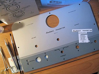
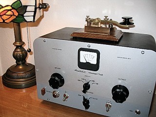
Sanding and painting the old panel wasn't a big job, but the decals presented a problem. You'll
notice in the picture to the right, the lack of 0-10 gradients around the tuning controls. The
reason for omitting these is the difficulty working with such large decals. You'll see on the
finished product that the circles around the band selector have also been omitted for the same
reason. However, if you have the patience, they are included on the decal templates available for
download below, but you're on your own.
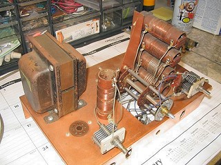
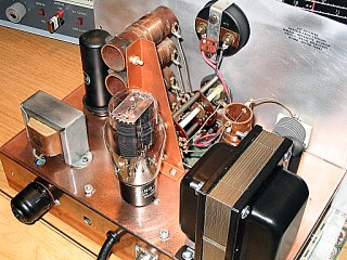
Pictures of the chassis before and after restoration are shown below.
BEFORE
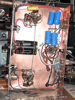
AFTER
BEFORE
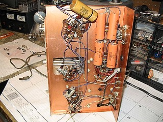
The chassis was completely stripped, cleaned and re-wired. The standard re-cap routine was performed, resistor values were checked and all controls were cleaned. Fuses and holders were added...one to the transformer primary and one to the high voltage secondary. Since holes were drilled, and non-original switches were used, I went ahead, replaced one, and added another. The cabinet and front panel were repainted, and decals added as mentioned before.
AFTER
The Finished Product
The following decal templates are presented as a guide only. It's best to make the graphics twice
the normal size and send the image to the decal paper at 50%. Print to regular paper first and make
final adjustments to the size.
I used Testors inkjet clear decal paper. After waiting for the printed image to dry for a couple
hours, I coated the paper with Testors Decal Bonder #9200, and let it dry for 12 hours.
DOWNLOADS:
Decal template 1
Decal template 2
Decal template 3
The AT-1 schematic diagram. Diagram of function
switch.
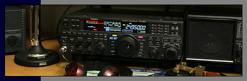
Note: Signal Electric (Menominee, Michigan) Navy Type key displayed on top of transmitter.

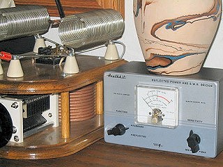
Heathkit Reflected Power and SWR Bridge
SPECIFICATIONS: Operation... Indicates percentage of forward and reflected power, and voltage
standing wave ratio (SWR). RF Power Handling Capabilities... One kilowatt. Input And
Output Impedance... 50 or 75 ohm. Band Coverage... 160 through 6 meters.
Dimensions... 7-3/4" wide x 4-5/8" high x 4-1/16 deep.
MISC: The circuit of the Reflected Power Meter and SWR Bridge is based upon that of a device
developed at the U.S. Naval Research Laboratory. As much as 75 watts may be needed on 80 meters for
full scale deflection, and as little as 2 watts on 6 meters.
Is it a rare Heathkit find or a long lost and forgotten prototype? No, but it is one of a kind, and
another example of working with what's given you.
This meter started off in life as an HM-11, but when I got it, it hardly resembled any known piece of
hardware, so I improvised. The meter was cracked and the knobs were missing, but the price was
right...free!
I painted the dented and scratched case to match the AT-1, replaced the meter with a NOS one from '61,
and finished it off with a couple AT-1 style knobs. I also changed the two 1N34A diodes to a
matched set, and calibrated the bridge.
A purest may not like reincarnating old gear, but in my opinion, it's better than throwing it in the
trash.
The AM-2/HM-11 schematic diagram.
The Whatever Wattmeter
")

