

 Station AJ8MH - Marquette, Michigan")
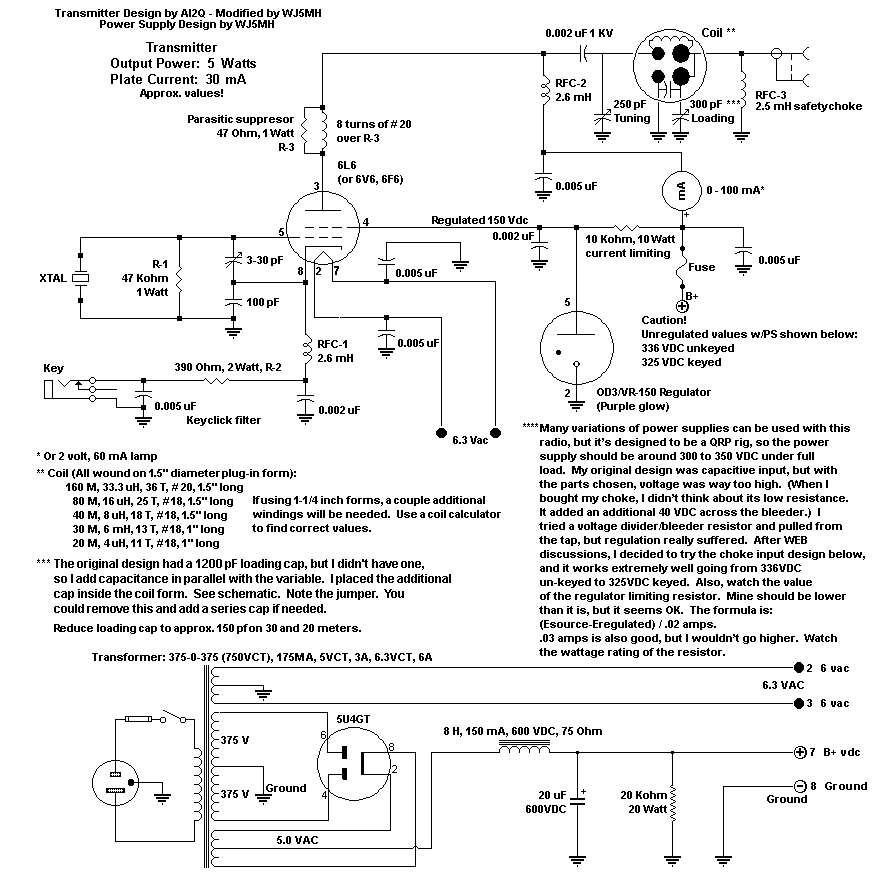
6L6GC Transmitter and 5U4 Power Supply
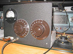
Homebrew 5U4 Power Supply
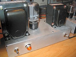
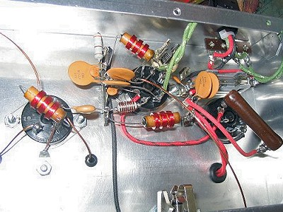
Homebrew 6L6GC Transmitter
Notes on single 6L6GC transmitter w/0D3A regulator, and 5U4 power supply.
Many handbooks don't mention the operating characteristics of single 6L6 or 6V6 transmitters, so let it
be known that a certain "touch" is needed to tune these. It just takes a little practice.
The oscillator is very sensitive to output tuning, so as you look for resonance (minimum plate current)
there is a good chance that oscillations will stop. I find it much easier to quickly tune for max
power out. Once there, the plate current is minimum, or close to it, and (of course) you have
oscillations. However, at this point your note may not sound very good...maybe a little
chirpy. To correct this instability, tune slightly to one side of resonance or the other to find
the best note. It's been suggested that the "C" side of resonance is best for both linked-tank or
pi-network tuning. A regulated screen voltage is also helpful.
Tuning will need to be touched up when you change from a dummy-load to your antenna system.
Complete transmitter and power supply schematics:
DOWNLOAD
(A Fluke 87 true RMS voltmeter was used for all measurements.)
P/S:
1) Power supply is a choke input design (8H, 75 Ohms, 150 mA, 600 VDC)
2) Using single 20 uF cap @ 600 VDC
3) Bleeder resistor is 20 K, 20 watt
4) Using 5U4GB with 375-0-375 V, 175 mA transformer)
Measurements - radio NOT keyed:
1) 336 VDC w/regulator in circuit
2) 1.45 VAC ripple
3) 178 VDC dropped across regulator 10K limiting resistor
4) About 17.8 mA. (Should make limiting resistor 6.2K, but 10K seems to work fine.)
5) 158 VDC regulated on screen
Measurements - radio keyed:
1) 325 VDC fully loaded
2) 1.56 VAC ripple (Transmitted note sounds good.)
2) Actual plate current 30 mA
3) Input power 9.75 watts
4) Output power 5.5 watts
5) 157 VDC regulated on screen
Top view w/loading cap at bottom.
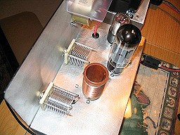
Top view L-R, 0D3A, 6L6GC, and coil.
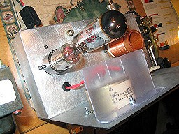
Bottom view of the 6L6 transmitter with its MANY components.

")

